

SURFACE RESIDUAL STRESS DISTRIBUTIONS IN AS-BENT INCONEL 600 U-BEND AND INCOLOY 800 90-DEGREE BEND TUBING SAMPLES
Paul S. Prevéy Lambda Research
ABSTRACT
Selected data showing typical macroscopic residual stress distributions in u-bent Inconel 600, and 90 deg. bends in Incoloy 800 are presented. The results indicate regions of both high magnitude tension and compression in the longitudinal direction around the circumference of the bends at the apex.
The microscopic residual stress, or percent plastic strain and macroscopic residual distributions in the surface of cross-roll straightened and ground Inconel 600 tubing are described. The results indicate a compressive surface layer accompanied by a yield strength gradient from 90 ksi at the surface to 30 ksi at a depth of 0.003 in.
PREFACE
THE DATA PRESENTED HERE REPRESENT A selected compilation of results of investigations of residual stress distributions in cross-roll straightened and ground Inconel 600 tubing, u-bent Inconel 600 tubing, and 90 deg. bends in Incoloy 800 tubing. The results represent a small fraction of the data obtained by the author to date in the investigation of residual stress distributions in tubing samples for various applications in the nuclear power industry.
The results presented here are considered to be typical of the types of residual macro- and microstress distributions observed and are available for publication with the consent of the sponsors of the original investigations in order to further the understanding of the residual stress distributions present in tubing manufactured from these alloys.
The influence of stress relieving heat treatment upon the residual stress distributions in bent tubing is obviously of interest in order to determine the
magnitude of the reduction of residual stress and its redistribution as functions of time and temperature. Only preliminary investigations of the influence of thermal stress relieving upon the stress distributions in tubing samples have been performed to date. The results of these investigations are not considered to be sufficiently complete to warrant publication at this time. Clearly, a complete systematic study of the influence of thermal stress relieving heat treatments on the residual stress distributions in tubing is warranted.
SAMPLE PREPARATION
The straight sample of Inconel 600 tubing which was employed for the study of the macroscopic residual stress and percent plastic strain (microstress) distributions as functions of depth was examined in the cross-roll straightened and ground condition as received from the mill. The straight tubing sample examined was nominally 0.625 in. in diameter with a 0.040 in. wall thickness. In the as-received condition, the 0.625 in. Inconel 600 tubing was reported to have a 0.2% yield strength of approximately 25 to 30 ksi.
An Inconel 600 2 1/2 in. u-bend sample was prepared from tubing having a nominal 0.75 in. O.D. and a 0.040 wall thickness. The u-bend sample was reportedly prepared from tubing in the mill annealed, cross roll straightened, and ground condition. The room temperature yield strength was assumed to be on the order of 25 to 30 ksi.
One sample of Incoloy 800 tubing with a nominal outside diameter of 1.00 in. and a 0.20 in. wall thickness was investigated. The sample was formed to a 90 deg./3D bend. The Incoloy 800 90 deg. bend sample was formed from material which was reportedly in the solution annealed and ground condition, with a yield strength on the order of 25 to 50 ksi.
"Workshop Proceedings: U-Bend Tube Cracking in Steam Generators," Electric Power Research Institute, Palo Alto, CA, (1981), pp. 12-3 to 12-19
EXPERIMENTAL METHOD
Subsurface Microscopic Residual Stress Distributions
The cross roll straightened and ground sample of 0.625 in. O.D./0.040 in. wall Inconel 600 tubing was employed to investigate the macroscopic and microscopic residual stress distributions as functions of depth to approximately 0.017 in. beneath the original ground surface. Both the microstress or degree of cold work and percent plastic strain, and the macroscopic residual stress were investigated so that both the state of macroscopic stress and the change in mechanical properties, such as yield strength, resulting from the plastic deformation which occurred during grinding could be determined.
Broadening of diffraction peaks as a result of plastic deformation resulting in disruption of the crystal lattice and increased dislocation density has been observed for years by many investigators. Line broadening data can be treated rigorously by the methods developed by Warren and Averbach(1) to determine the contributions to peak broadening from crystallite size reduction, percent plastic strain, and instrumental broadening. A rigorous analysis of this type requires extensive data collection and exhaustive data reduction. Because the crystallite size contribution tends to be insignificant in the high back-reflection region, where data were collected for this investigation, and because the results could be obtained with fixed x-ray optics and slit systems providing a constant instrumental broadening, it appeared that simple measurement of the diffraction peak widths during the course of the measurement of macroscopic residual stress would suffice, provided an empirical relationship was established between the magnitude of the microscopic residual stress, or percent plastic strain, present in the samples and the diffraction peak width measured.
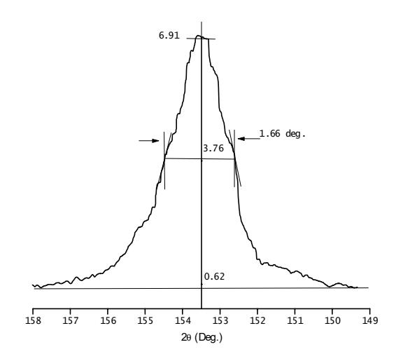
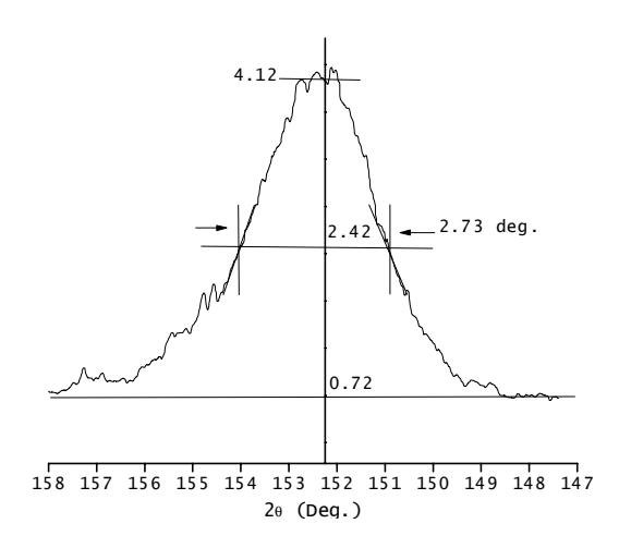
A technique for both macro- and microscopic residual stress measurement employing the diffraction of chromium K-β radiation from the (311) diffraction peaks was adopted in order to avoid complications arising from doublet separation when using the copper K-α technique normally employed for stress measurement in these alloys. Examples of the (311) diffraction peak obtained with chromium K-β radiation for a sample exhibiting approximately 15% plastic strain and one exhibiting approximately 40% plastic strain are shown in Figures 1 and 2, respectively.
An empirical relationship between the percent plastic strain on the surface of the sample and the FWHM of the (311) diffraction peak obtained with chromium K-β radiation was developed using samples of 0.625 in. diameter Inconel 600 tubing which were first annealed and then elongated in tension to known levels of plastic strain. The results and the calibration curve developed are shown in Figure 3. The angular width of the (311) diffraction peak was determined at two locations rotated 90 deg. around the circumference of the tubing samples employing both 1 deg. and 3 deg. divergent beams which resulted in approximately an order of magnitude increase in the diffraction peak intensity obtained. It was found that for tubing subjected to plastic strains of approximately 2, 4, 8, and 16%, a linear relationship was obtained between the width of the (311) diffraction peak and the plastic strain level. An attempt was made to subject a sample to 32% plastic strain, but necking resulted which is believed to be the cause of the deviation from a linear relationship. The strain level was also found to be significantly different between locations 1 and 2 measured on the 32% sample indicating nonuniform strain around the circumference. A discontinuity in the linear relationship was observed between 0% and 2% plastic strain. The same nonlinearity had been observed subsequently in data of this type developed for other nickel base alloys.
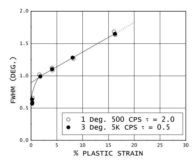
The results of a least squares fit to the data between 2 and 16% plastic strain provide an empirical relationship between the percent plastic strain on the surface of the sample and the FWHM of the (311) diffraction peak of
This relationship was then used to calculate the percent plastic strain as a function of depth in conjunction with the measurement of macroscopic residual stress.
Macroscopic Residual Stress Measurement
The macroscopic residual stress was determined in the
0.625 in. diameter Inconel 600 tubing sample at the surface and as a function of depth to nominally 0.017 in. beneath the sample surface in the direction parallel to the longitudinal axis of the tubing. X-ray diffraction residual stress measurements were made by the Two-Inclined Angle technique(2) employing the diffraction of chromium K-β radiation from the (311) planes of the FCC structure of the Inconel 600 alloy. The diffraction peak angular positions were determined employing a five-point parabolic regression procedure after correction for the Lorentz-polarization and absorption effects, and for a linearly sloping background intensity.
The value of the elastic constants E/(1 + ν) for the crystallographic direction normal to the (311) planes of the Inconel 600 alloy was determined experimentally in the course of the investigation by loading a simple rectangular beam manufactured from Inconel 600 in four-point bending on the diffractometer and determining the change in the lattice spacing of the (311) planes as a function of applied stress. The method employed to determine the x-ray elastic constants E/(1 + ν) in the (311) direction required to calculate macroscopic residual stresses from strains measured in the crystal lattice has been described previously(3).
Material was removed for subsurface measurement by electropolishing in a sulfuric acid-methanol electrolyte minimizing possible alteration of the subsurface residual stress distribution as a result of material removal. The macroscopic residual stress data obtained as a function of depth were corrected for the effects of the penetration of the radiation employed for stress measurement into the subsurface stress gradient(4) and for stress relaxation which occurred as a result of material removal.(5)
X-ray diffraction residual stress measurements were made on the surface only of the u-bent Inconel 600 tubing sample in the longitudinal direction as a function of circumferential position around the u-bend apex. Measurements were made by the Two-Inclined Angle technique employing the diffraction of copper K-α radiation from the (420) planes. Residual stress measurements were made on the Incoloy 800 90-deg. bend sample in both the circumferential and longitudinal directions on the surface only at the apex of the bend by the Two Angle technique, employing the diffraction of chromium K-α radiation from the (220) planes. For both the copper K-α and chromium K-α techniques, the x-ray elastic constants E/(1 + ν) were determined empirically in the manner described above.
Because all measurements made on the bent tubing samples yielded surface data only, it was not possible to correct those results for the influence of the penetration of the radiation employed for stress measurement into the subsurface stress gradient.
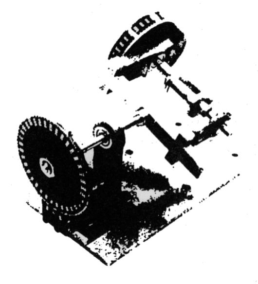
Based upon the earlier work by Berge, et al., (6) a pronounced stress gradient was anticipated around the circumference of the bent tubing samples examined. Therefore, a special positioning fixture was constructed, as shown in Figure 4, which would allow the positioning of the tubing with an accuracy on the order of ± 0.5 deg. for residual stress measurements in either the longitudinal or circumferential direction around the circumference of the tubing at the apex of the bend
Because of the geometry of the bends, only approximately a 1 in. length of the tubing could be mounted in the fixture, requiring sectioning of the bend samples. Electrical resistance strain gages attached to the surface of the bent tubing samples during the sectioning operation indicated stress relaxations in either the longitudinal or circumferential direction on the order of ± 1.0 ksi, less than the anticipated random error of approximately 3 ksi in the x-ray diffraction technique, and substantially less than the overall accuracy of approximately ± 5 ksi. Therefore, the tubing samples were sectioned and mounted in the fixture by potting the sections to a shaft which was then turned in a four-jaw chuck so that the axis of rotation was coincident with the center of the elliptical perimeter of the bent tubing.
RESULTS AND DISCUSSION
Subsurface Residual Macroscopic and Microscopic Residual Stresses in Straight Inconel 600 Tubing
The results of both the microscopic residual stress, determined from the measured FWHM of the (311) diffraction peak, and the longitudinal macroscopic residual stress as functions of depth to approximately 0.017 in. beneath the surface of the ground sample of straight Inconel 600 tubing are shown in Figure 5. The results are presented in terms of the percent plastic strain, and the residual stress in units of ksi (103 psi). Compressive stresses are shown as negative values, tensile as positive.
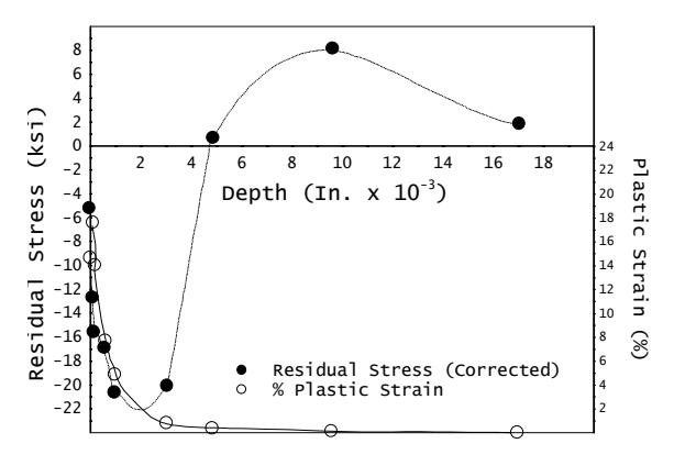
The results indicate compressive macroscopic residual stresses ranging from approximately -5 ksi at the surface to -21 at a depth of approximately 0.002 in. beneath the surface. The residual stress distribution then rises to cross the zero-stress axis approximately 0.005 in. beneath the surface. A peak tensile stress on the order of 8 ksi was observed at a depth of 0.010 in. beneath the surface, which diminished in magnitude with increasing depth.
The plastic strain was found to be approximately 16% at the surface and decreased exponentially as a function of depth to insignificant amounts at a depth of 0.005 in. beneath the surface.
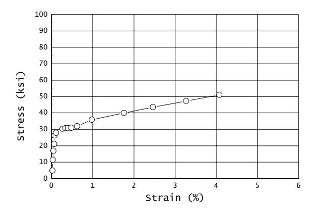
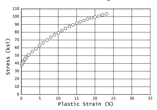
The percent plastic strain as a function of depth can be expressed as a variation in yield strength with depth based upon the known stress-strain behavior for Inconel 600 tubing. Stress-strain relationships for Inconel 600 tubing are shown for total strain ranges of
approximately 4% and 25% in Figures 6 and 7, respectively. It is apparent from the results shown in Figure 7 that Inconel 600 material which has been subjected to 20% plastic strain would have a yield strength on the order of 100 ksi. This represents approximately a factor of 4 increase in yield strength compared to the original mill annealed condition.
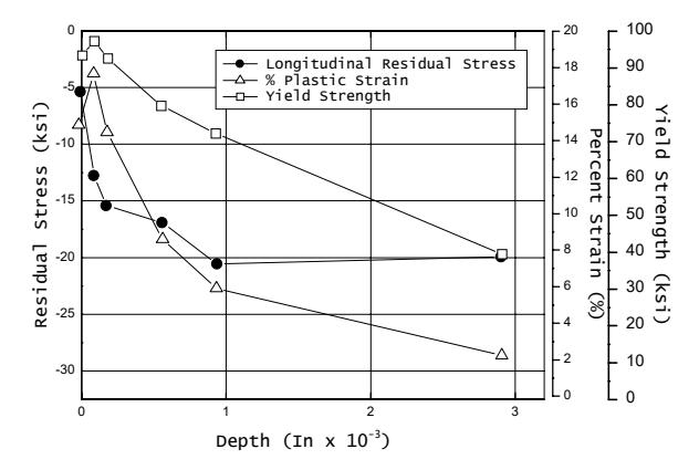
The macroscopic residual stress, percent plastic strain, and the corresponding yield strength gradient based upon the data shown in Figures 6 and 7 are presented in Figure 8 on an expanded scale for the first approximately 0.003 in. beneath the ground surface of the straight Inconel 600 tubing. The results indicate a nearly linear decrease in yield strength with depth. The yield strength was found to range from approximately 95 ksi at a depth of 0.0001 in. beneath the surface to approximately 35 ksi, on the order of the mill annealed condition, at a depth of approximately 0.003 in.
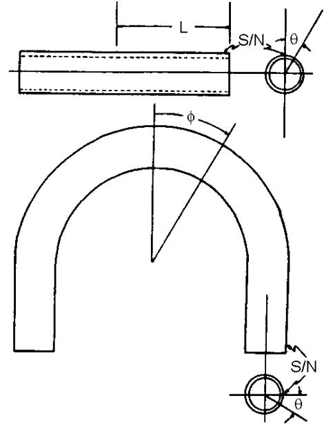
The coordinate system used for defining the stress measurement sites on bent tubing samples presented here is depicted in Figure 9. For both the u-bent and 90 deg. bends of Inconel 600 and Incoloy 800 tubing respectively, the results shown here were obtained at the apex of the bend at the position φ = 0. The angle, θ, around the circumference of the tubing was taken to be zero at the extrados of the bend. The results are presented in here in terms of the parameter (1 + cos θ ) in the manner of Berge, et al.(6)
The macroscopic residual stress results obtained in the longitudinal direction around the circumference of a single sample of 2 1/2 in. u-bent Inconel 600 tubing are presented in Figure 10. The data shown as open circles indicate the 0 to 180 deg. range. Measurements were made near the neutral axis of the bend and near the extrados and intrados through the 180 to 360 deg. range and are shown as closed circles.
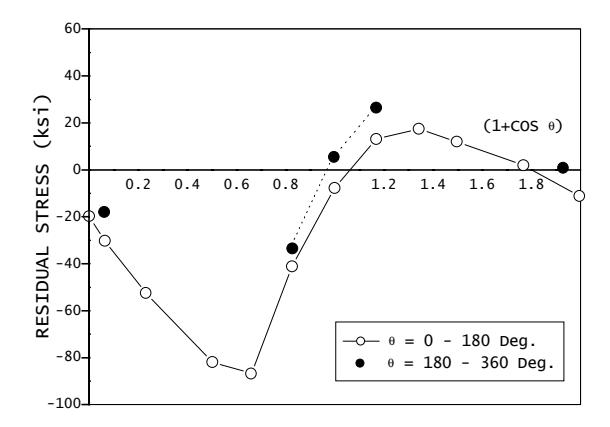
The longitudinal results indicate generally tensile residual stresses ranging from the extrados to the neutral axis (1 + cos θ = 2.0 to 1.0) with maximum tensile stresses on the order of 15 to 30 ksi occurring in the neighborhood of (1 + cos θ) = to 1.3. The stress distribution then changes very rapidly into compression near the neutral axis of the tubing achieving peak compressive stresses on the order of -85 ksi for (1 + cos θ) of approximately 0.7. The intrados of the bend was found to be approximately -20 ksi in compression. The compressive stress of -10 ksi measured at (1 + cos θ) = 2.0, the extrados, may be the result of a burnishing of the surface of the tubing which occurred during the bending operation.
The data shown in Figure 10 indicate an increase in yield strength of the surface layers, probably due to prior grinding, on the order of a factor of 3 greater than the mill annealed condition.
Surface Longitudinal and Circumferential Residual Stresses on a 90 Deg./3D Bend in Incoloy 800 Tubing
The longitudinal residual stress distribution around the circumference of the 1.00 in. diameter 90 deg./3D bend Incoloy 800 tubing sample are shown in Figure 11. The residual stress results show an oscillating pattern of stress entirely in tension from the extrados of the tubing to just beyond the neutral axis. Peak tensile stresses on the order of 80 ksi were observed immediately adjacent to the neutral axis. An extremely rapid change in stress was observed at the neutral axis, with peak compressive stresses on the order of -80 ksi occurring just below the point of transition at approximately (1 + cos θ) = 0.75. The region from the neutral axis to the intrados was found to be entirely compressive with approximately -20 ksi present on the intrados of the tubing.
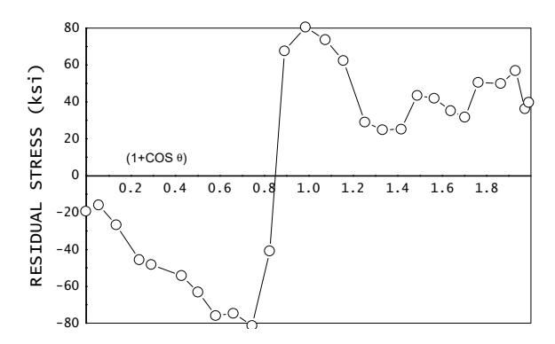
The oscillations observed in the longitudinal residual stress distribution from the extrados to the neutral axis may be the results of local variations in residual stress and yield strength as the result of work hardening caused by processing of the tubing prior to bending. Local stress variations of this type have been observed in the past on ground surfaces.(7) The magnitude of the residual stress present on the surface of the tubing after bending indicates an increase in yield strength on the order of at least a factor of 2 for the surface layers of the Incoloy 800 tubing. It may be that the surface of the Incoloy 800 tubing prior to bending contained a residual stress and yield strength gradient not unlike that previously described for the straight sample of Inconel 600 tubing.
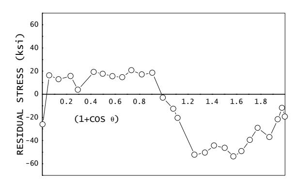
The results obtained in the circumferential direction at the apex of the 90 deg./3D bend are presented in Figure 12. The results show entirely compressive stresses from the extrados to the neutral axis with a peak compressive value on the order of -50 ksi occurring at approximately (1 + cos θ) = to 1.6. Oscillations similar to those observed in the longitudinal direction occur from the extrados to the neutral axis in the circumferential direction. The circumferential residual stress distribution becomes tensile from the neutral axis to near the intrados with a nearly constant stress distribution on the order of 15 to 20 ksi. The intrados was found to be approximately -25 ksi in compression, which may be the result of local deformation or burnishing during the bending operation.
CONCLUSIONS
The results shown for the subsurface residual macroscopic and microscopic residual stresses produced by grinding straight 0.625 in. diameter Inconel 600 tubing indicate increases in yield strength from nominally 30 to 90 ksi at the ground surface. The yield strength gradient diminishes nearly linearly to reach the nominal mill annealed value of approximately 30 ksi at a depth of 0.003 in. The residual stress distribution associated with the grinding operation was found to be entirely compressive to a depth of approximately 0.005 in., with low magnitude tensile stresses beneath.
Examination of a 0.75 in. O.D. Inconel 600 tubing 2 1/2 in. u-bend shows entirely compressive stresses reaching magnitudes as high as -85 ksi from the intrados to the neutral axis, and tensile stresses reaching 20 ksi from the neutral axis to the extrados. An extremely large stress gradient exists in the vicinity of the neutral axis.
An even larger stress gradient exists in the vicinity of the neutral axis, and higher magnitude tension and compression, on the nominally 1 in. diameter Incoloy 800 90 deg./3D bend were examined. Oscillations observed in the stress pattern in both the longitudinal and circumferential directions at the surface may be the result of variations in surface residual stress and yield strength caused by grinding the surface prior to forming the bend.
ACKNOWLEDGEMENTS
The straight 0.625 in. diameter Inconel 600 sample was supplied by The Babcock & Wilcox Corporation, who supported the investigation of the subsurface macroscopic and microscopic residual stress distributions. The u-bent Inconel 600 tubing residual stress distributions were obtained during research sponsored by Combustion Engineering, who supplied the 0.75 in. diameter u-bend sample. The work on Incoloy 800 tubing 90 deg./3D bends was supported by The General Atomic Company who supplied the sample for the investigation.
The author gratefully acknowledges the support of the individual sponsors and expresses his appreciation for permission to publish these results.
REFERENCES
-
- B.E. Warren and B.L. Averbach, J. Appl. Physics, Vol. 20, P. 885 (1949).
-
- M. E. Hilley, J.A. Larson, C. F. Jatczak and R. E. Richlefs, editors Residual Stress Measurement by X-ray Diffraction, SAE J784a (1971).
-
- P.S. Prevéy, "A Method of Determining the Elastic Properties of Alloys in Selected Crystallographic Directions for X-Ray Diffraction Residual Stress Measurement," Adv. in X-ray Analysis, Vol. 20, P. 345-354 (1977).
-
- A.L. Christenson, et al., "The Measurement of Stress by X-Ray," SAE TR-182, P. 23-24, (1960).
-
- M.G. Moore and W. P. Evans, "Mathematical Correction for Stress in Removed Layers in X-Ray Diffraction Residual Stress Analysis, SAE Trans., Vol. 66, (1958).
-
- Berge, Bui, Donati and Dillard, "Residual Stresses in Bent Tubes for Nuclear Steam Generators," Corrosion, NACE Vol. 32, 9, (Sept. 1976).
-
- P.S. Prevéy and M. Field, "Variation in Surface Residual Stress Due to Metal Removal," Annals of the CIRP, Vol. 24 P. 497-501, (1975).